
PGT120 ESD Tester Mounting Options
- Best placement for efficient testing.
- Mounting of accessories such as RFID readers, Data Terminals, Printers or Signal Lamps (if using).
- Access to power. The PGT120 can be battery operated but the PGT120.COM requires an outlet/AC power. Data Terminals and some accessories also require AC power
- Access to Ethernet. For some installations, the Data Terminals require an wired connection to the network.
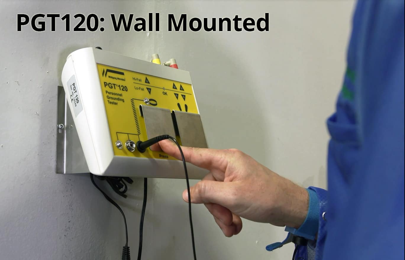
Wall Mounted
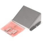
To save valuable space, the PGT120 can be mounted to the wall. The wall mounting plates is model number: 7100.PGT120.WK.
Pedestal Mounted
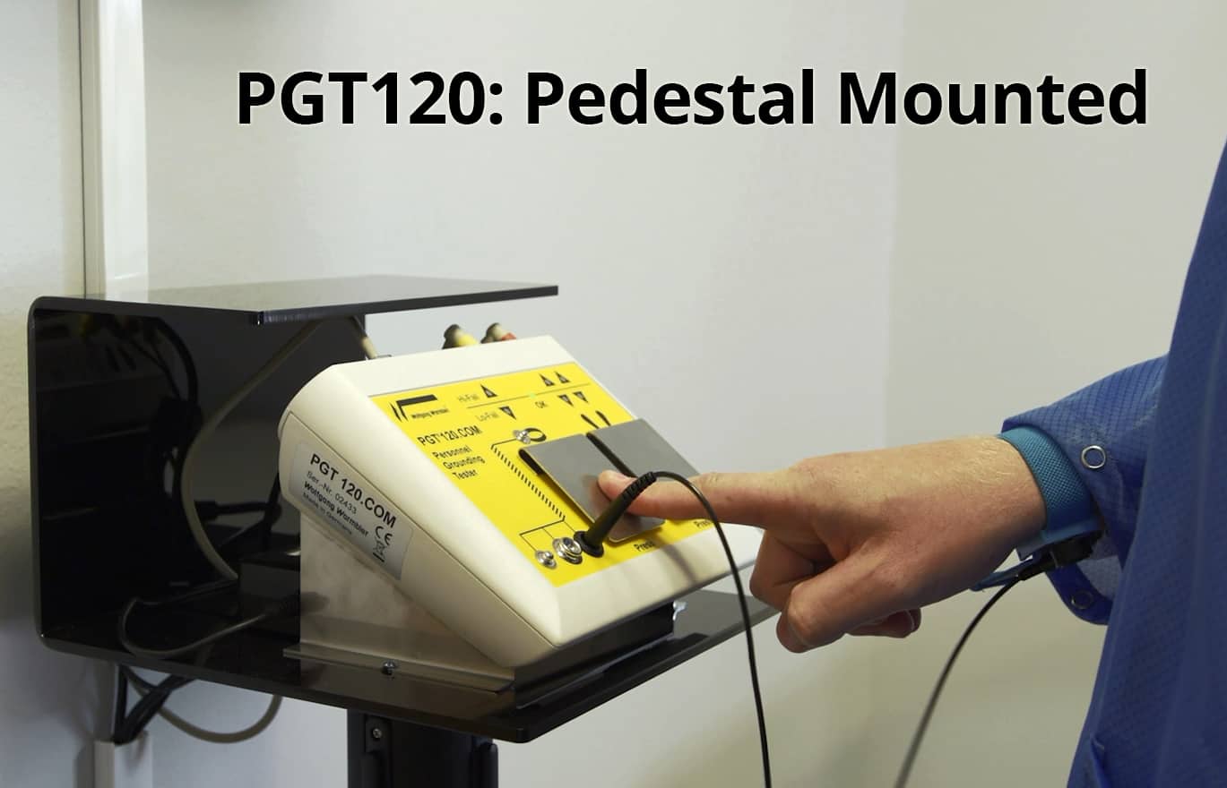
The PGT120 can be installed on a free standing pedestal. The pedestal stand is part number: 7100.PGT120.SE:
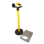
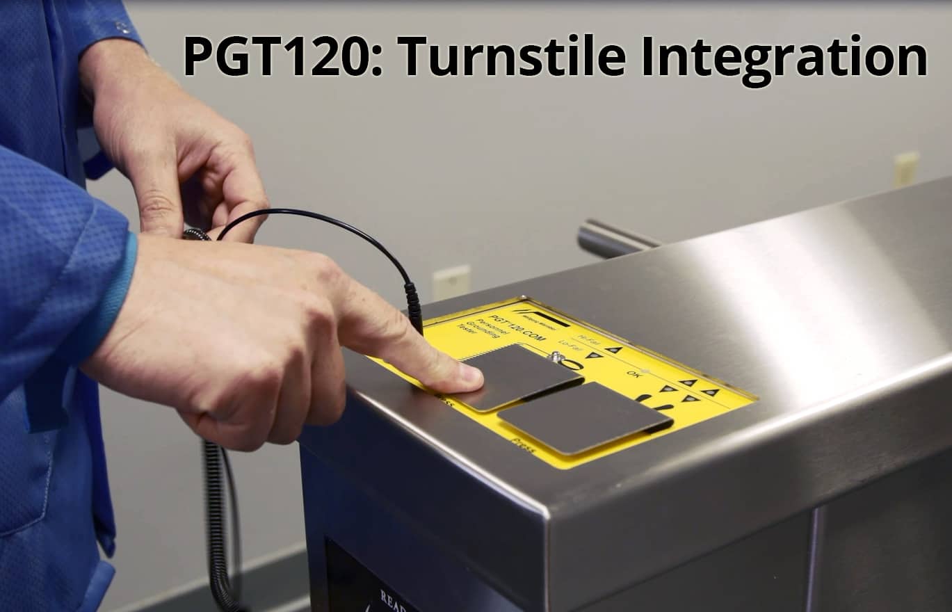
Turnstile Integration
The PGT120 can be integrated into barrier systems such as a door, gate or turnstile. The PGT120 includes a NO/NC switch. If using the PGT120.COM with a data terminal, the system requires a relay module cable: part number 7100.PGT120.TEST.12. Transforming Technologies offers a turnstile system. called the AccessPRO.
Pedestal Stand Assembly Instructions
If you are installing your PGT120 tester as a free-standing pedestal mounted unit, you can download the installation instructions here:
PGT120-Stand-Installation-Instructions – Transforming Technologies
Web Interface: How To Find Your IP Address:
The web interface for the PGT120.COM is reached via a web browser through an IP address. Each PGT120 testing system on your network (you can have up to 32) will be assigned an unique IP address. An IP Addresses is a series of numbers used to identify devices on a network. An IP address should automatically be assigned to the DT by your internet router when plugged into the network (most common set up). That number is entered into a web browser to bring up the Web Interface. (If not assigned, the default IP address for the DT is 192.168.1.1).
If the default IP address does not bring up the Web Interface, there are four methods to find your IP address:
- Router: If you have web access to your router, you may connect to your router and find the IP addresses of all networked devices.
- 3rd Party Program: Use an IP search tool such as the free Advanced IP Search program. Download here: https://www.advanced-ip-scanner.com/
- Label Printer: The IP Address will automatically print out if using the label printer(may take up to 50 seconds).
- Command Line Prompts
We demonstrate each method in the video below:
NOTE: Set Your Own IP Address: It is possible to enter a different IP-Address manually. However this is not recommended during the Quick Start because the DT will not be accessible any more in case of false configuration and must be manually reset. Read section “Manual IP-Address Configuration” for this. Alternatively you could prefix a router with required functionality. Entering a fixed IP-Address will deactivate DHCP.
Navigate your PGT120.COM's Network Web Interface:
Each DT is controlled through the Web Interface (which is accessed through a unique IP address). If you have multiple DTs in a building, each system has their own unique web interface and are controlled independently. If you have more than one tester in a facility, the Daeman software can control the whole group (see Dataterm section for more information).
The first access opens the configuration page without asking for a password. The default login is User: admin and the Password: admin.
The password can be changed at a later date.
- Type the IP address into a web browser and hit enter.
- Set the DT’s Time Zone, Date and Time in the System Setting.
- Measurement data – “footwear in series” must be set according to the connected PGT120.COM DIPswitches.
- After saving the settings you find the two optional sections Network and Advanced in the Configuration
menu.Optional settings: - If desired you can configure a fixed IP-Address in section Network section of the manual.
- Settings for User data synchronization are available in section Advanced section of the manual.
View the Web Interface in Video Below:
VIDEO HERE:
NOTE: Set Your Own IP Address: It is possible to enter a different IP-Address manually. However this is not recommended during the Quick Start because the DT will not be accessible any more in case of false configuration and must be manually reset. Read section “Manual IP-Address Configuration” for this. Alternatively you could prefix a router with required functionality. Entering a fixed IP-Address will deactivate DHCP.
PGT120.COM - Software Installation & User Data:
Each DT is controlled through the Web Interface (which is accessed through a unique IP address). If you have multiple DTs in a building, each system has their own unique web interface and are controlled independently. If you have more than one tester in a facility, the Daeman software can control the whole group (see Dataterm section for more information).
The first access opens the configuration page without asking for a password. The default login is User: admin and the Password: admin.
The password can be changed at a later date.
- Type the IP address into a web browser and hit enter.
- Set the DT’s Time Zone, Date and Time in the System Setting.
- Measurement data – “footwear in series” must be set according to the connected PGT120.COM DIPswitches.
- After saving the settings you find the two optional sections Network and Advanced in the Configuration
menu.Optional settings: - If desired you can configure a fixed IP-Address in section Network section of the manual.
- Settings for User data synchronization are available in section Advanced section of the manual.
View the Web Interface in Video Below:
VIDEO HERE:
PGT120.COM - Documents and Owners Manuals
Each component of the PGT120.COM systems has its own manual. Follow the Quick Start Guide to install the tester and review the manuals for more in depth information. Not all systems will include the same components, so not all documents may be relevant to your installation.
Use the following links to download PGT120.COM supporting documents.
PGT120 & PGT120.COM Owners Manuals
- PGT120 Tester – Non Data Logging Tester – Owners Manual
- PGT120.COM Tester – Data Logging Tester – Owners Manual
Mounting
- How to Assemble the PGT120 Stand – Manual
Data Terminals Owners Manuals
- Data Terminal 2 – Standard – Owners Manual
- Data Terminal TC18 – Touch Screen Computer – Owners Manual
PGT120 Software
- Software – Owners Manual
User Data Set Up
- User Data Excel Template – Excel File
